Coaxial Collinear Antenna for ADS-B Receiver.
Dusan Balara
balarad@balarad.sk
The original antenna obtained with the ADS-B receiver AirNav( RadarBoxPRO is so great product that it is hard to build a better home made omnidirectional antenna with a higher gain than the original one. During my almost one year period of experiments with various types of antennas I built only one which fulfilled this expectation - it is the coaxial collinear antenna.
Concept of construction.
The main component for the building is a 75 Ohm coaxial cable used for the satellite TV or 50 Ohm coaxial cable. Another components are a connector type F or SMA, insulating tape, PVC pipe with the outer diameter 12 mm and suitable end-seal for this pipe. The necessary tools are the caliper, sharp knife, scissors, glue for PVC and the ohmmeter. The basic element of the coaxial collinear antenna is coaxial cable (Figure 1) with the length calculated from the wave length of the ADS-B signal.
The wave length of the signal is
lambda = c/f
where is velocity of the electromagnetic signal,
in the vacuum, i.e. c = 300 000 [millions meters per sec],
is frequency of the ADS-B signal, i.e. f = 1090 MHz,
so that wave length lambda is 275 mm.
The length L of the basic element is the half wave length reduced by the velocity factor of the coaxial cable (the velocity of the electromagnetic waves in the coaxial cable is lower). I used the 75 Ohm cable RG-6U/32FD with the velocity factor 0.85 and 50 Ohm cable Tri-Lan 240 with the velocity factor 0.83 and I used the same element length for both cables, i.e. L=0.5*275mm*0.85=116 mm.
Figure 1 The basic element of the antenna.
The basic elements are connected to the chain in which the outer conductors and inner conductors are counterchanged between two adjacent elements (Figure 2).
Figure2 Coaxial collinear antenna.
Such assembled elements are still the coaxial line. This line is connected to the receiver with the balanced input 50 Ohm impedance. My experiments indicated that it is beneficial to connect outer and inner conductors on the opposite end with the 75 Ohm or 50 Ohm to preserve the VSWR near 1.
Construction of the Antenna.
I recommend to have the inner element conductor longer about 50 mm (Figure 3) on both sides than the part with the outer conductor to enable good contact with the outer conductor of the adjacent element and also make assembled elements rigid.
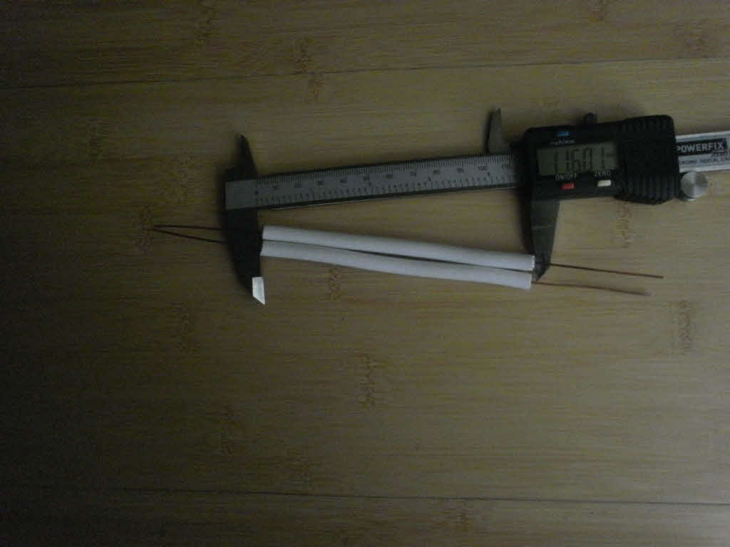
Figure 3 The basic elements before connecting.
Insert the small tape piece between two elements before connecting them.
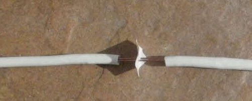
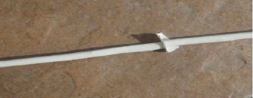
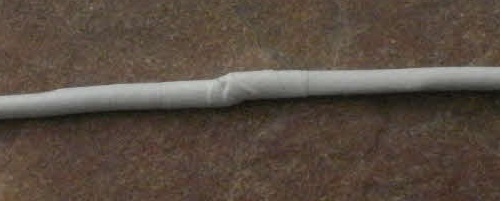
Figure 4 Connecting of the basic elements.
(Video file of the basic elements connecting for the AVI files player.)
Check connected elements with the ohmmeter before final assembling because there are many possibilities to make short connection between conductors and it is a problem to find such a connection if antenna is finally assembled. It is comfortable to begin assembling from the first element with the balance resistor and check if there is 75 Ohm or 50 Ohm between conductors.
The assembled antenna is terminated with the "F" or SMA connector and inserted into the PVC pipe.
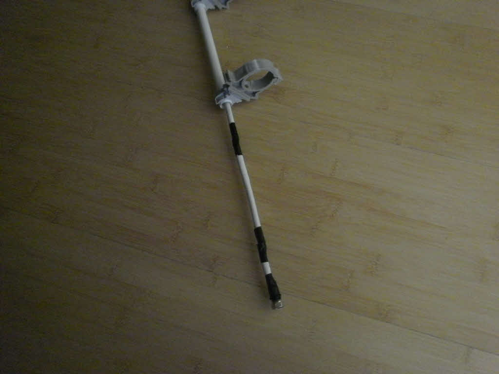
Figure 5 Assembled antenna.
The 16 elements antenna fits to the 2 m long pipe, 8 elements fits to the 1 m long pipe. The "F" or SMA connector is fixed with the insulation tape and PVC glue to the pipe.
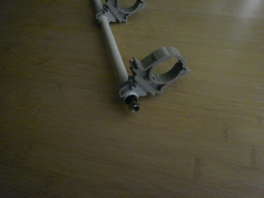
Figure 6 Fixing of the antenna F connector.
The opposite end of the pipe is covered with the end-seal.
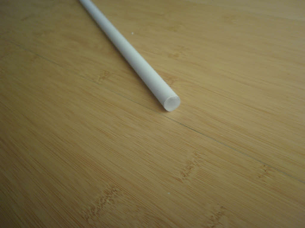
Figure 7 End - seal of the pipe.
Antenna is used in the vertical position due to the polarization of the ADS-B signal.
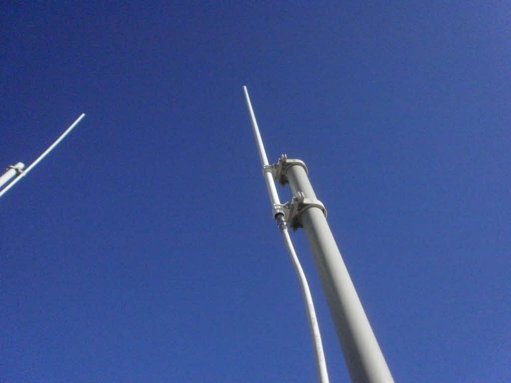
Figure 8 Antenna mounted on the mast.
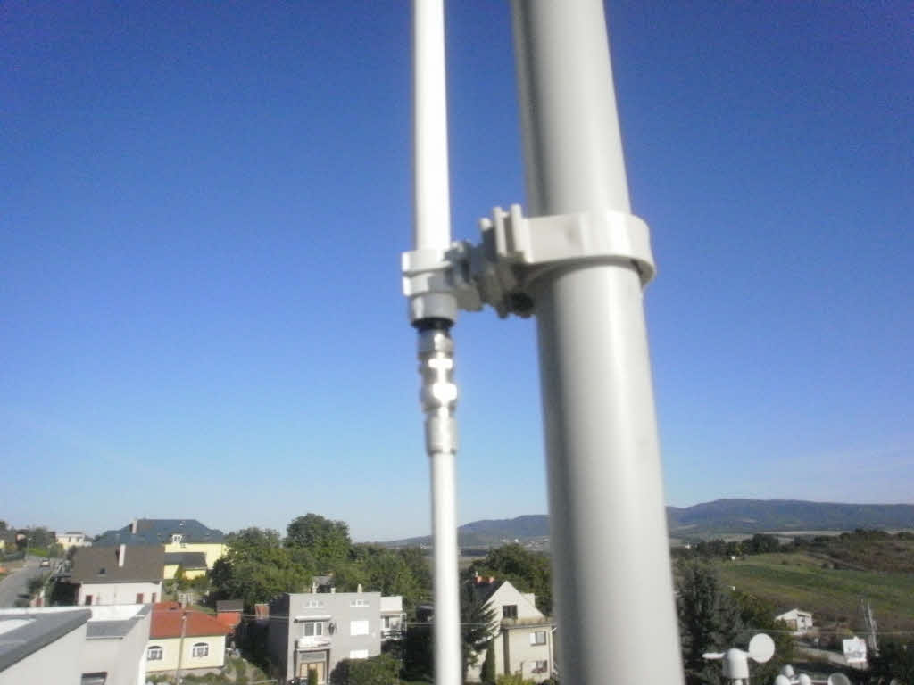
Figure 9 Connection of the feed line.
Lightning and Static Electricity Protection.
There may be applied four barriers against lightning and static electricity between antenna and input of the ADS-B receiver.
The first barrier is PVC pipe by which is collinear coaxial antenna covered. This barrier avoids mainly damage caused by discharging of the static electricity of the body of the person who manipulates with the antenna, but also is the barrier against lightning.
The second barrier is lambda/4 protection stub (Figure 10).
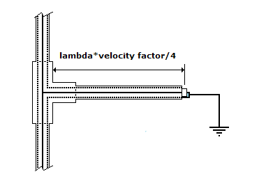
Figure 10 lambda/4 protection stub.
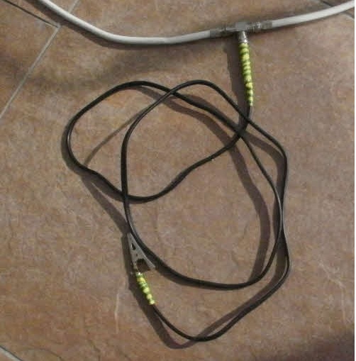
Figure 11 View of the lambda/4 protection stub.
The stub is a coaxial line with the short connection on the end and is connected to the feeding coaxial line via "T" element of the "F" connector on the opposite end. Its length is velocity factor*lambda/4 = 58.5 mm. Due to the theory of the coaxial lines such stub is parallel resonant circuit, i.e. its impedance is very high for the frequency 1090 MHz. For higher or lower frequency the impedance is very low. More ever, the end with the short connection may be connected to the earth and by this way drain out static electricity. Using of such stub doesn't cause the significant decreasing of the antenna gain.
The third barrier could be the signal amplifier. I used the usual TV antenna amplifier with the frequency range from 47 MHz until 862 MHz, gain 20 dB and impedance 75 Ohm. Except amplification of the signal the amplifier will become with high probability "the victim" of the lightning and such damage is easier replaceable and is not expensive as is the ADS-B receiver replacement. The amplifier is very useful for the fourth barrier 75/50 Ohm transformer (the more details below). The apparently not sufficient amplifier frequency bandwidth is not important. The ADS-B frequency 1090 MHz is only 26,5% higher than the highest amplifier TV working frequency, but it doesn't mean that it is really the highest frequency which can be transferred and amplified by it. If we assume that amplifier is first order dynamical system with the decrease -3dB at 862 MHz, the decrease at 1090 MHz would be only -4 dB, i.e. your amplifier doesn't have gain 20 dB, but "only" 16 dB.
The fourth barrier is 75/50 Ohm transformer (Figure 12).
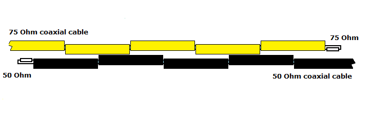
Figure 12 75/50 Ohm transformer.
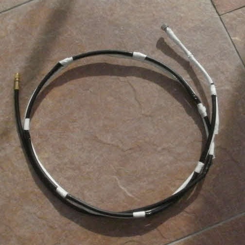
Figure 13 View of the 75/50 Ohm transformer.
It consists from the two parts, each is coaxial collinear antenna. The first collinear antenna is built from the 75 Ohm coaxial line and is balanced with the 75 Ohm resistor, the second collinear antenna is built from 50 Ohm coaxial line balanced with the 50 Ohm resistor. They are applied to themselves as close as possible with the mutual half element shift. The signal from the 75 Ohm part of the transformer is transferred to the 50 Ohm part very effectively without galvanic connection. More ever, the 50 Ohm receiver input is matched to the 75 Ohm circuit of the antenna or amplifier output, there is not combination of the 75 Ohm and 50 Ohm lines and loads. The small loss of the signal power caused by this transformer can be compensated by the amplifier.
The Results of the Tests.
I have tested coaxial collinear antenna with the 16 elements in the four configuration. The tests were made in the position N 49.1421, E 20.2404 on the piedmont of the hill Slavkovsky stit (High Tatras in Slovakia) on the altitude 950 m over the sea. Before the tests the 24 hours polarogram of the original antenna was measured. The feed line was long approximately 5 m.
The first configuration.
ADS-B receiver was connected to the coaxial collinear antenna, the lambda/4 protection stub was applied (Figure 14). The test was running 24 hours without interrupt. The weather was fairly well with blue sky and sun shining, without clouds, rains or storms, with slight wind, temperature varied in the range from 12 until 24 deg C .
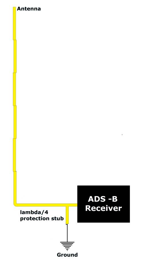
Figure 14 First configuration - coaxial collinear antenna connected to the ADS-B receiver via lambda/4 protection stub.
Figure 15 Polarograms of the original antenna and the coaxial collinear antenna - the first configuration.
The second configuration.
ADS-B receiver was connected to the coaxial collinear antenna via 75/50 Ohm transformer, the lambda/4 protection stub was applied (Figure 16). The test was made 6 hours without interrupt. The weather the same as was during the first test.
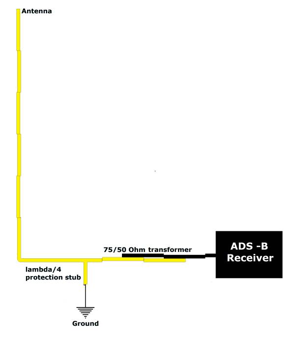
Figure 16 Second configuration - coaxial collinear antenna connected to the ADS-B receiver via lambda/4 protection stub and 75/50 Ohm trasformer.
Figure 17 Polarograms of the original antenna and the coaxial collinear antenna - the second configuration.
The third configuration.
ADS-B receiver was connected to the coaxial collinear antenna via amplifier, the lambda/4 protection stub was (Figure 18). The test was made 24 hours without interruption. The weather was the same as during the first test.
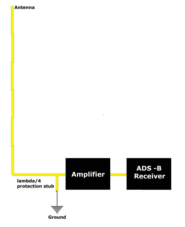
Figure 18 Third configuration - coaxial collinear antenna connected to the ADS-B receiver via lambda/4 protection stub and amplifier.
Figure 19 Polarograms of the original antenna and the coaxial collinear antenna - the third configuration.
The fourth configuration.
ADS-B receiver was connected to the coaxial collinear antenna via amplifier, the lambda/4 protection stub was applied on the input of it, the 75/50 Ohm transformer was applied between amplifier and receiver (Figure 20e). The test was made 12 hours without interrupt. The weather the same as during the first test.
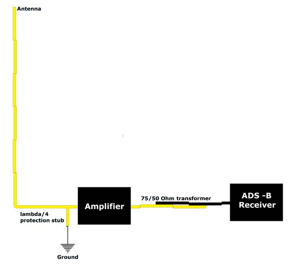
Figure 20 Fourth configuration - coaxial collinear antenna connected to the ADS-B receiver via lambda/4 protection stub, amplifier and 75 Ohm/50 Ohm transformer.
Figure 21 Polarograms of the original antenna and the coaxial collinear antenna - the fourth configuration
Some Final Conclusions.
1 - It seems that the optimal configuration is fourth. The polarogram indicates high sensitivity. The triple protection barrier against lightning and static electricity decreases probability of a damage.
2 - The experiments of the coaxial collinear antenna with the 8, 16 and 32 elements indicate that the amount of elements over 16 doesn't bring significant effect on the antenna gain but the length over 2 m becomes not acceptable. The good compromise is 12 elements antenna - its gain and length 1.5 m are acceptable.
3 - The optimal installation of the antenna is on the non conducting elastic mast.
4 - The mechanical performance of the antenna is very simple and elegant. Its shape makes it proof against strong wind.
Appendix after one year of experiments.
I have tested antennas with the 8,12 and 16 elements and have found that more than 12 elements don't bring significant change of the polarogram. From the mechanical point of view the optimal antenna is with the 8 elements - it fits to 1 meter long tube.
The terminal resistors are not mandatory to achieve high sensitivity of the antenna and good transfer of the 75/50 Ohm transformers - their ends could be opened. However the resistors are useful for the monitoring of the conductivity of the antenna and transformer elements and also for discharging of the inducted static electricity.
As optimal configuration has been found the following:
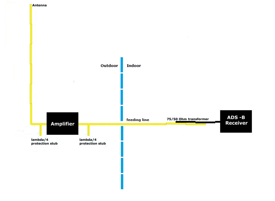
Figure 22 Optimal configuration - coaxial collinear antenna connected to the ADS-B receiver via lambda/4 protection stub on the amplifier input , amplifier, lambda/4 protection stub on the amplifier output and 75 Ohm/50 Ohm transformer.
Amplifier is situated as near to the coaxial collinear antenna as is possible. First lambda/4 protection stub is on the amplifier input, the second on the amplifier output. This part of the antenna is situated outdoor on the mast and is connected with the indoor part with the feeding line. Indoor part consists of 75/50 trasformer and ADS-B receiver. Such configuration has good gain and the polarogram is similar to one on the Figure 15. The main advantage of this is the robustness against static electricity inducted on the antenna. Lambda/4 protection stubs are not grounded not to provoke direct lightning strike into antenna. The 75/50 Ohm transformer and indoor environment separate the ADS-B receiver from the outdoor danger of static electricity and lightning.
This configuration is working safely during storm without freezing or damage of the ADS-B receiver. Also outdoor amplifier on the mast is safely protected thanks to lambda/4 protection stubs.
Related author's web sites:
Comparison of the mismatched and pure 50 ohm coaxial collinear antennas for ADS-B receivers.
Related web sites:
Making an inexpensive 1090MHz ADS-B collinear antenna
Project 9: A coax collinear antenna for ADSB
Hak5 1606 – How To Build An ADS-B Antenna
Constructing an ADS-B Collinear Antenna